Redundancy solution for multiple antennas serving an n+1 configuration
Executive Summary
High uptime is critical for most satellite ground station signals. Failure of a single device in the transmission chain can disrupt large arrays of service. This creates the need for a smart, automated, backup protection system.
To meet application-specific requirements for satellite earth stations and L-band distribution systems, redundancy switches offer important advantages for operators. A single motorized antenna can serve an entire dish farm as a backup antenna protecting multiple primary dishes. Signal monitoring, control and switching of a backup antenna can be offloaded to a redundancy switch to secure a cost-effective, simple-to-use solution offering a highly robust redundancy system.
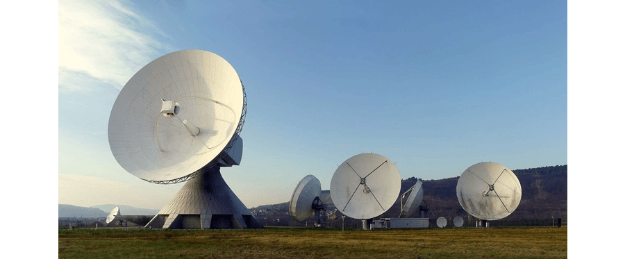
Fig.1: Satellite Earth Stations in Raisting, Germany
Introduction
Satellite ground stations demand high uptime. Spare devices in “hot standby” are thus used to ensure system uptime. In rare cases, 1:1 redundancy may be required for each antenna in the system array. However, for most requirements, several antennas may share a single redundancy antenna.
One common setup comprising six Ku-band antennas, each with four L-band signals (Horizontal High, Horizontal Low, Vertical High, Vertical Low) is backed up by one redundant antenna. This arrangement called “4*6+1” protects six primary signal paths using a single redundancy antenna path (6+1). Four of these channel redundancy units, one for each polarization (4*), are configured within a single switch.
DEV has developed a single switch to handle all of these features. Up to four redundancy units each serving 16 signal channels are possible (4*16+1).
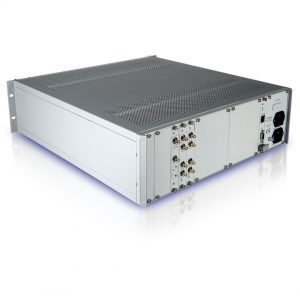
The DEV 1993 is specified for frequencies up to 2.45 GHz and is available in 50 ? with SMA connectors or in 75 ? with precision F connectors. High isolation separating the distinct service channels from the redundancy channel is attained to ensure optimal signal quality.
Local setup and control for the device is implemented by a web interface for configuring, switching and monitoring the device.
This product can also be expanded to set up and steer a motorized backup antenna via controller to create an operator-free backup system switching signals from any failed antenna to the spare path.
Operation of the redundancy switch
In normal operating mode where antennas function fully, each signal is delivered to its chosen output. When an antenna fails, the backup dish recovers the feed of the failed antenna. Signals from the redundancy antenna should thus be routed to the output ports of the replaced dish to provide a hot-standby recovery of service.
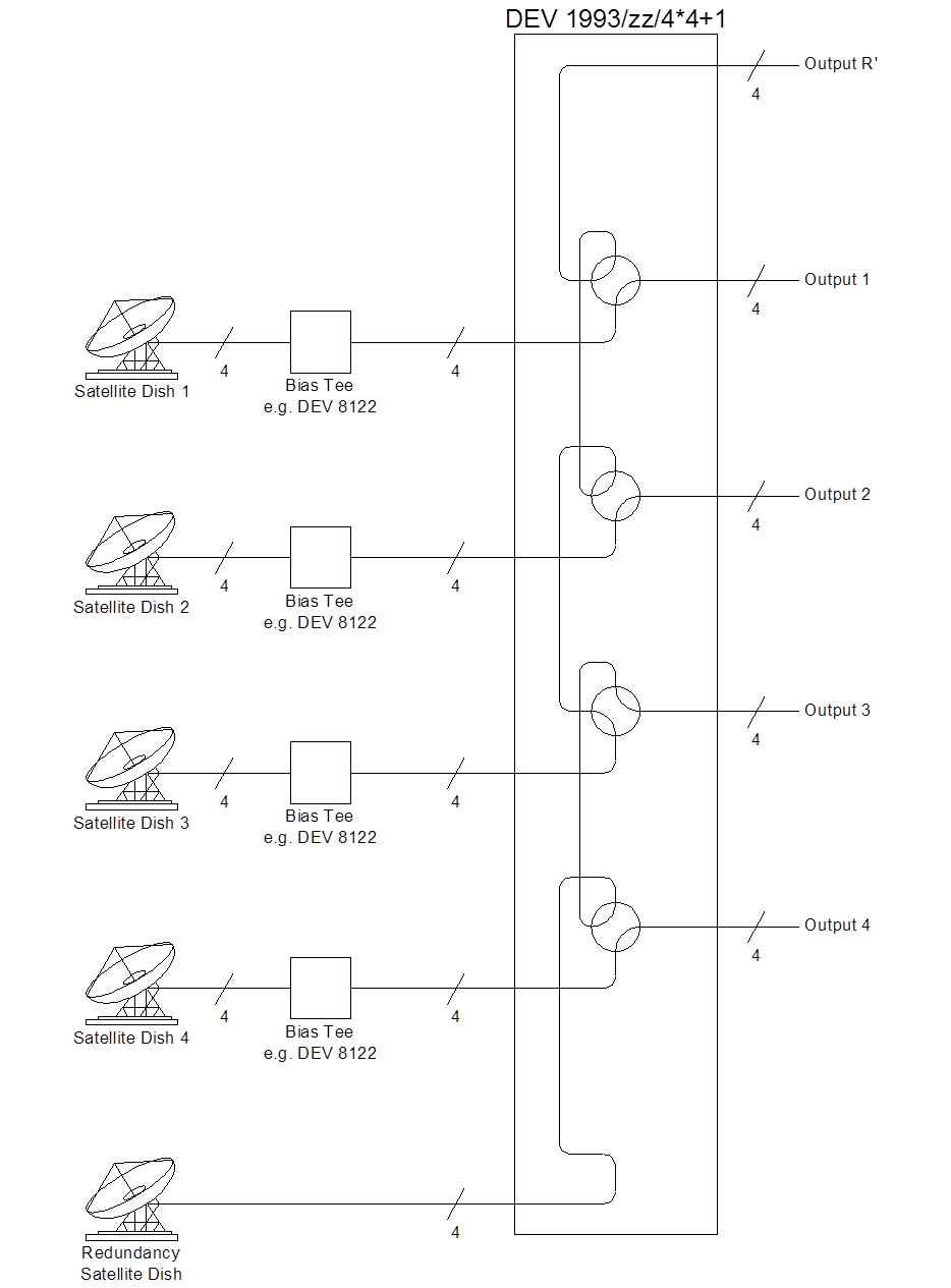
Fig.2: Using a Motorized Redundancy Antenna
During normal operation, the signals of the redundancy antenna are routed to Output R (Figure 2) where the signal can be monitored. This is especially necessary when the redundancy antenna is motorized to adjust to the positions of each satellite serving the fixed antennas. Here, signal strength can be assessed before switching to redundancy.
Figure 2 shows a 4+1 antenna system utilizing a DEV 1993 configured for 4*4+1. Note that the bias supply for the redundancy antenna is provided by the DEV 1993.
Monitoring & Control of a Motorized Antenna
To significantly improve the uptime of a facility having multiple fixed satellite antennas, one or more motorized steerable antennas can be used as a redundant spare. When a fixed antenna fails, the steerable antenna restores signal by pointing at the satellite(s) normally served by the failed antenna.
If a fixed antenna’s L-band signal fails, the backup antenna must be commandeered to the satellite position of the lost feed, typically via its Antenna Control Unit (ACU). In addition, a redundancy switch must engage so that the signal captured by the redundancy antenna will reach its proper destination. Manual recovery is typically slower than automatic switching and requires continuous attendance by a human operator. Furthermore, in most cases, an ACU cannot be easily served by a redundancy switch.
The objective behind DEV Systemtechnik’s development of its antenna monitoring and control option has been to provide a comprehensive and powerful automatic solution for n+1 redundancies. Here, a system needs the ability to aim a motorized redundancy antenna automatically to specific satellite positions stored within the DEV 1993. Another requirement involves switching redundant signals to the same outputs fed by a primary stationary antenna.
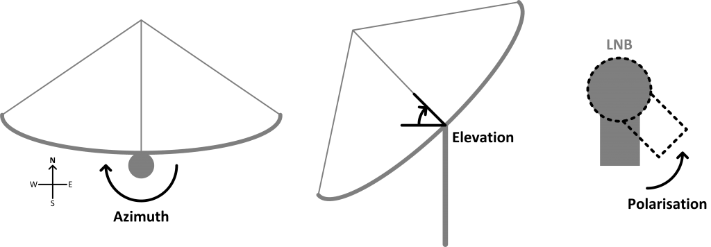
Fig.3: Azimuth, Elevation and Polarization Angel
The position of an antenna, especially a motorized one, can be described by three angles. The azimuth (AZ) sweep of the whole antenna about its vertical axis starts clockwise at geographical North (0 deg.) to end at 360 deg. Elevation (El) refers to the angle between the satellite beam and horizontal plane. Finally, the polarization angle (Pol) – not to be confused with the mere polarity of a received signal – marks the rotation of the LNB away from its normal position, ranging from -90 deg. (counterclockwise) to 90 deg. (clockwise). Notably, not all ACUs support control of the LNB polarization angle.
Figure 4 illustrates the components of an antenna system with four stationary antennas backed up by one motorized redundancy antenna. The RF outputs (four signals per antenna) of all antennas are connected to the redundancy switch. The motion of the motorized antenna in terms of azimuth, elevation, and (possibly) the polarization is controlled by the DEV 1993 through an ACU.
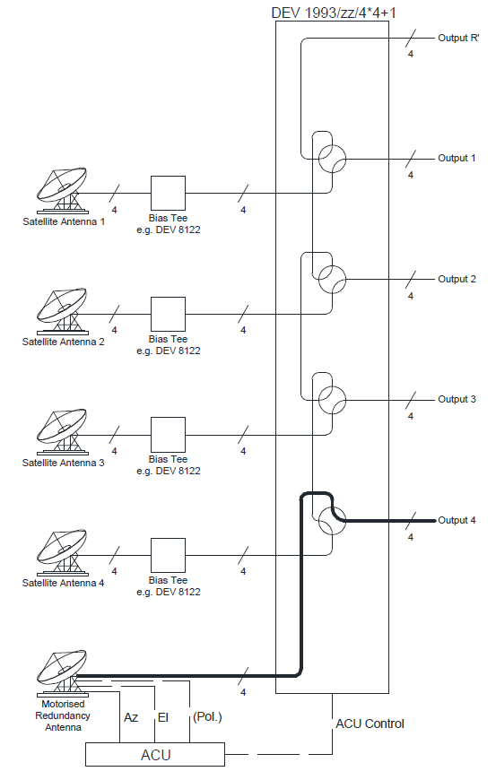
Fig.4: Backup system using a Motorized Redundancy Antenna
Using the global position of the antenna site, the DEV 1993 can calculate the distinct antenna positions (AZ, El and Pol) for each different satellite as shown in Figure 5. The position of each stationary antenna is then stored for commanding the ACU to position the motorized redundancy antenna. Switched inputs are finally fed by the redundancy antenna to the corresponding outputs.
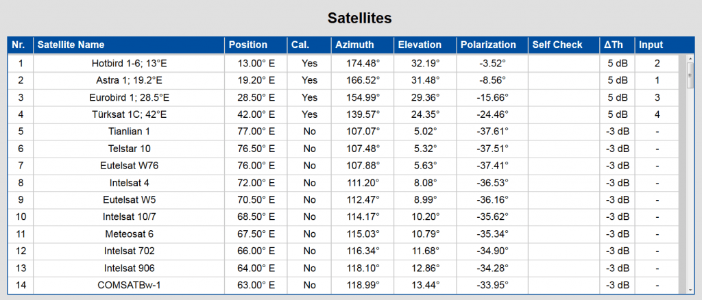
Fig.5: Satellite Position stored within the DEV 1993
Figure 4 shows Output 4 of the DEV 1993 being fed by the Motorized Redundancy Antenna after the failure of primary Satellite Antenna 4. Here, the system has already positioned the Motorized Redundancy Antenna to the coordinates required to back up primary Antenna 4, having switched the four signals to the redundant routing.
Note: The applied antenna controller needs to be connected to the CPU module.
Note: The signals of Satellite Antenna 4 are not routed to Output R when the device is switched to the redundant mode, as may be implied by Figure 4.
Dual Band Redundancy
Consider, for example, a satellite ground station having 10 Ku-band antennas using all four polarizations plus six C-band antennas with two polarizations. The goal here is to ensure antenna redundancy enlisting only one additional motorized antenna.
To fulfill this requirement, the redundancy antenna is equipped with a dual-band feedhorn system to handle Ku- and C-band signals of both frequency ranges and is motorized for quick positioning.
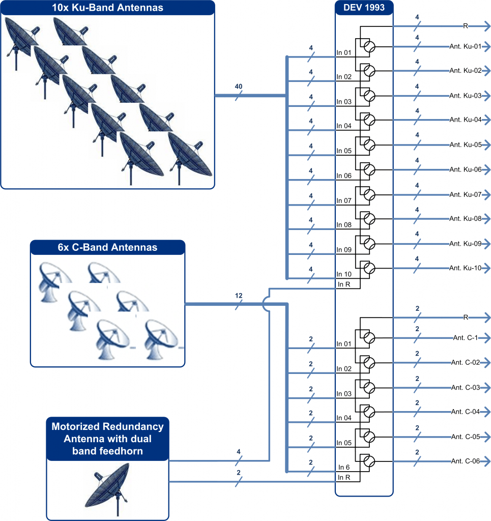
Fig.6: Dual Band Redundancy
The DEV 1993 serves as a redundancy switch for the 4*10+1, 2*6+1 array to link all antennas to the corresponding input of the device. It also controls the motorized antenna via the corresponding ACU. Powering of both LNBs for the backup antenna is supplied by the DEV 1993.
In normal operating mode, the steerable redundancy antenna is automatically aimed to the various satellite positions in regular intervals to check for any error or malfunction. Received signals can be monitored at Output R of the DEV 1993 via spectrum analyzer using the built-in RF sensing function. For this routine, the DEV 1993 checks all positions serving the stationary antennas. Of course, the motorized antenna can also be moved manually using the web interface or the ACU.
In cases of fixed antenna failure – either a bad LNB or cabling trouble – the DEV 1993 drects the ACU to aim the backup antenna to the lost satellite position(s). Irrespective of Ku- or C-band antenna failure, all incoming backup signals are checked. When confirmed, the device performs a switching action and connects the backup antenna with the outputs served by the primary antenna. As a result, signal outage time is minimized.
The switching philosophy emulates the DEV 1993, absent the dual-band configuration: only one output for either redundancy is switchable to the redundancy antenna, and this device requires switching to normal operation mode before a different channel can be routed to redundancy.
After checks and repairs are performed at the failed antenna, the DEV 1993 can then be switched back to normal operation mode manually.
Summary
To assure continuous uptime of dish farms required by satellite services and their users, redundancy systems are crucial. Manual recovery of antenna service via redundant backup is time consuming, and automation often involves a complicated solution.
Steerable motorized antennas offer redundancy for larger dish farms. Added dual-band feedhorns enable a backup antenna to restore various antennas serving multiple frequency bands. Yet, control of these backup antennas can still prove quite difficult.
A cost-effective, reliable, and efficient solution meeting this challenge enlists a smart redundancy antenna switch such as the DEV 1993. Signal loss on any primary antenna is automatically detected, and the DEV 1993 can be configured to aim a backup antenna for automatic recovery of lost feed. Since the primary function of the 1993 is to command switching functionality, the restored antenna signal arrives at its proper output. To ensure “hot-standby” mode for the redundant antenna, the DEV 1993 also supplies LNB power.
Dual-band redundancy systems serving Ku- and C-band antennas are also configurable. These switches invoke a simple, complete and reliable system for even the most demanding satellite ground stations.
About DEV Systemtechnik: DEV Systemtechnik develops and manufactures a complete range of products and systems for the optical and electrical transmission of Radio Frequency (RF) signals via coaxial cable or fiber. For over 20 years DEV has designed, engineered, and manufactured RF transmission equipment for satellite, broadcast, and cable applications. All products are built to meet the highest standards of system availability, reliability and manageability.
More Information? Please contact:
DEV Systemtechnik GmbH
Email: info@dev-systemtechnik.com
Phone: +49 (0) 6031/ 6975-100
Fax: +49 (0) 6031/ 6975-114
www.dev-systemtechnik.com